Overview
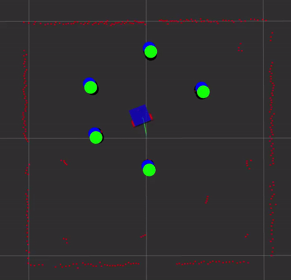
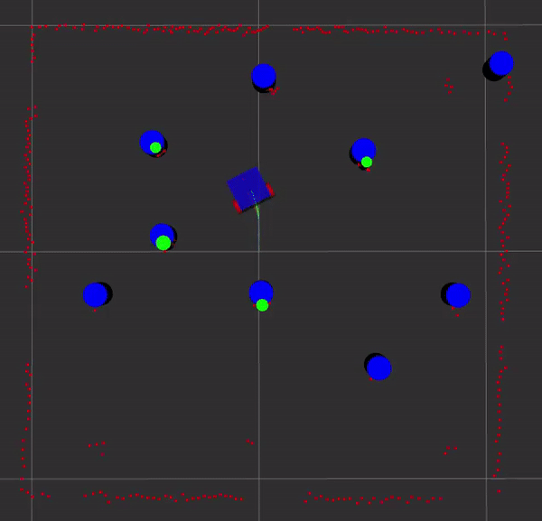
The orange path is gazebo, the green path is odometry, and the blue path is EKF slam. The blue cylinders are the landmarks estimated by EKF slam and the green cylinders are either from the feature detector or from gazebo. See the code in my GitHub repository.
Here is EKF SLAM with known and unknown data association. The ground truth path from Gazebo is in orange, SLAM in blue, and odometry is green. The landmark estimates from EKF SLAM are blue and the detected landmarks are shown in green.
EKF SLAM
Feature detection
The laser scan was clustered using a distance threshold between points in the scan. Circles were fitted to each cluster using the algorithm presented in [1].
Algorithm
The algorithm is divided into two steps: state update and measurement update. The state estimate is the same for both.
The robot’s state is updated using a probabilistic motion model. Here the belief \(\xi_t^{-}\) is the state estimate, \(g\) is a motion model, \(u_t\) is the body twist, and \(\epsilon\) is the motion model noise.
\[\begin{equation} \hat{\xi_t^-} = g(\hat{\xi}_{t-1}, u_t, \epsilon) \end{equation}\]Next, propagate the uncertainty using the linearized (via Taylor-Series) state transition model:
\[\begin{equation} \hat{\Sigma_t^-} = g'(\hat{\xi}_{t-1}, u_t, \epsilon) \ \hat{\Sigma}_{t-1} \ g'(\hat{\xi}_{t-1}, u_t,\epsilon)^T + \bar{Q} \end{equation}\]The process noise \(Q\) is a diagonal matrix corresponding to the Gaussian noise for the robot’s pose \((x, y, \theta)\) :
\[\begin{equation} \bar{Q} = \begin{bmatrix} Q & 0_{3x2n} \\ 0_{2nx3} & 0_{2nx2n} \end{bmatrix} \end{equation}\]Known Data Association
For each measurement, \(i\) assoicated with landmark \(j\), compute the Kalman gain \(K\).
\[\begin{equation} K_i = \Sigma_t^- h_j' \ (\xi_t)^T (h_j' \ (\xi_t) \ \Sigma_t^- \ h_j'(\xi_t)^T + R)^{-1} \end{equation}\]Use the measurement model to predict the observation given the current belief and update the state posterior.
\[\begin{equation} \hat{z_t}^i = h_j(\hat{\xi_t^-}) \end{equation}\] \[\begin{equation} \hat{\xi_t} = \hat{\xi_t^-} + K_i (z_t^i - \hat{z_t^i}) \end{equation}\]Finally, compose the posterior covariance.
\[\begin{equation} \Sigma_t = (I - K_i h_j'(\xi_t)) \Sigma_t^- \end{equation}\]Unknown Data Association
The data association is accomplished using the Mahalanobis distance.
Iterate over the number of observed landmarks \(N\) where \(k\) is the landmark number. First compute:
\[\begin{equation} \psi_k = h_k’(\hat{\xi_t}^-) \ \Sigma_t^- \ h_k’(\hat{\xi_t}^-)^T + R \end{equation}\]Calculate the predicted measurement \(\hat{z_t^k}\) as described above.
\[\begin{equation} \psi_k = h_k’(\hat{\xi_t}^-) \ \Sigma_t^- \ h_k’(\hat{\xi_t}^-)^T + R \end{equation}\]Compute the Mahalanobis distance and append to a vector of measurements.
\[\begin{equation} d_k = (z_i - \hat{z_k}) \psi_k (z_i - \hat{z_k})^T \end{equation}\]Let \(d^*\) be the minimum Mahalonbis distance in the measurement vector at index \(j\). If \(d^*\) is smaller than the lower-bound Mahalonbis threshold, then j is the index used in the measurement update. If it is greater than the upper-bound Mahalonbis threshold, then \(j = N\) and increment \(N\).
Odometry
The diff_drive performs the Turtlebot’s odometry. The primarly purpose of this class is to convert wheel velocities to a body twist \(V_b\) and then integrate the twist to get the pose.
The distance between each wheel to the center is \(d\) and the wheel radius is \(r\). The transform from the left wheel to the base is \(T_{1b} = (0, 0, -D)\) and the transform from the right wheel is \(T_{2b} = (0, 0, D)\)
Twist to Wheels
The adjoints are:
\[\begin{equation} A_{1b} = \begin{bmatrix} 1 & 0 & 0 \\ -D & 1 & 0 \\ 0 & 0 & 1 \end{bmatrix} \end{equation}\] \[\begin{equation} A_{2b} = \begin{bmatrix} 1 & 0 & 0 \\ D & 1 & 0 \\ 0 & 0 & 1 \end{bmatrix} \end{equation}\]The twist of each wheel is written as \(V_i = A_{ib} V_b\):
\[\begin{equation} V_1 = \begin{bmatrix} w_z \\ r \dot{\phi_1} \\ 0 \end{bmatrix} \end{equation}\] \[\begin{equation} V_2 = \begin{bmatrix} w_z \\ r \dot{\phi_2} \\ 0 \end{bmatrix} \end{equation}\]The wheel velocities can be written as:
\[\begin{equation} \dot{\phi_1} = \frac{1}{r} \begin{bmatrix} -D & 1 & 0 \end{bmatrix} % \begin{bmatrix} w_z \\ v_x \\ v_y \end{bmatrix} \end{equation}\] \[\begin{equation} \dot{\phi_1} = \frac{1}{r} \begin{bmatrix} D & 1 & 0 \end{bmatrix} % \begin{bmatrix} w_z \\ v_x \\ v_y \end{bmatrix} \end{equation}\]Wheels to Twist
The matrix \(H\) maps the twist to the wheel velocities.
\[\begin{equation} \begin{bmatrix} u_L \\ u_r \end{bmatrix} = \begin{bmatrix} \dot{\phi_1} \\ \dot{\phi_2} \end{bmatrix} = H \begin{bmatrix} w_z \\ v_x \\ v_y \end{bmatrix} \end{equation}\] \[\begin{equation} H = \frac{1}{r} \begin{bmatrix} -D & 1 & 0 \\ D & 1 & 0 \end{bmatrix} \end{equation}\]To obtain the body twist, we must take the pseudo-inverse \(H^{+}\). The pseudo-inverse is based on the rows because the column approach results in a singular matrix.
\[\begin{equation} V_b = H^{+}u \end{equation}\] \[\begin{equation} H^{+} = H^{T}(HH^{T})^{-1} \end{equation}\]Credits
[1] Al-Sharadqah, Ali; Chernov, Nikolai. Error analysis for circle fitting algorithms. Electron. J. Statist. 3 (2009), 886–911. doi:10.1214/09-EJS419. PDF